
The base for the table has a few requirements. I wanted it to be wide to be as supportive as possible because it needs to fit in the footprint of the table when small but be amply wide when the table is large. I also wanted to make the base easy to disassemble as I can foresee needing to put this table on display a few times in a few different places.
The first step is to break out the parts from the rough boards. Using full size templates I traced out the needed parts to ensure efficient wood use and the best possible grain orientation for the different parts. Most of the stock I had available was quarter sawn and I wanted to use that for the legs to show the beautiful straight grain.
 |
| Planning the Cuts for Initial Stock Break Down |
In addition to the legs themselves I needed to make a central hub for them to attache to. The hub measures approximately 10" x 10" x 6". This block was assembled from 5 layers of wood 2" thick.
 |
| Building up the Block for the Central Hub in the Base |
Once this block was built up the joinery was cut into it. There are 4 mortises 2" x 2" x 0.5" deep. The legs join into each of these and are held into place with knock down bolts. This necessitates the large access cross on the underside of the hub. I forgot to take more pictures of the process but the hub corners were mitered off and the top surface domed over on the lathe.
 |
| Joinery of the Central Hub as Seen From Below |
The legs need to be 3" thick so some 8/4 stock was glued up to get to the needed thickness. The stock was milled down to the needed 3" and then the parts roughed out on the bandsaw. Just like the process used to create the curved components for the perimeter ring, the final shape is pattern matched on the router.
 |
| Initial Stock Glue Up |
Once the final shape has been established the leg components are all 3" by 3" in cross section. To create the joint between the foot and the leg a set of four floating tenons are used. This allows for lots of glue area and to keep the strength of the joint and simplifies construction.
 |
| Using the Horizontal Mortiser |
A pair of lines matching the location of the router bit is drawn onto the vertical board, as long as these are matched with the lines for the joint the floating tenons mate together quite nicely.
 |
| The Width of the Tenon Drawn in and Referenced to the Router Bit Width |
 |
| Joinery Completed and Ready for Assembly |
 |
| Four Floating Tenons in Each Joint for Strength |
The end grain at the end of the legs is quite weak because of the curve it is subjected to. To fix this weakness the short end grain is mitered off and a wedge of parallel grain is added to the foot. Any flex that the joint is subjected to will be withstood better and the components less prone to chip out. These end grain transition blocks will be sawn and sanded to a fair curve after which a quarter sawn skin will be applied to the front surface of the legs.
 |
| Mitering the Tip of the Leg to Remove the Weak Short Grain |
 |
| Completed Miter |
 |
| The Legs Glued Up |
 |
| Adding in Transition Block to Reduce Short Grain |
 |
| The Transition Block in Place and Ready for Fairing |
 |
| Batch Sanding the Curves of the Legs |
Once all the components were built the legs were assembled so that the locations for the mounting bolts could be marked. Fortunately everything came together great and the centers of the legs were a match for the mounting bolt locations. Once marked, the base was disassembled and the bolt mounting holes were drilled from the top and mortised from the backs of each leg.
 |
| The Base Initially Set Up to Test the Joinery |
 |
| Drilled Out Locations for Mounting to the Support Plate |
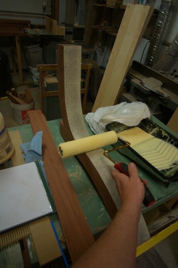
Just like the perimeter ring a skin of quarter sawn stock was veneered over the front face of the legs. To facilitate the moderately tight portion of the curve the skins were pre-bent by steaming them until moisture came through the piece and clamped to a legs for a day.
 |
| Steaming the Skins to Facilitate Bending |
 |
| Clamping the Skins During Bending |
 |
| The Bent Skins for the Legs |
Once the pre-bend is completed the skin can be clamped with cauls to the legs and left for a day for the glue to fully set. The skin overhangs the legs about 1/4" along the edges so it is trimmed flush and then a light chamfer is applied to the legs to help protect the edges. Also, a strong chamfer is added to the undersides of the feet.
 |
| Clamping the Skin Onto the Face of the Leg |
 |
| A Leg Out of the Clamps with the Skin Attached |
 |
| Trimming the Overhang of the Skin |
 |
| A Finished Leg |
No comments:
Post a Comment