Thursday 6 June 2013

The Table is Finished!!!

Sort of.  

On Monday morning I dropped off the components for the table at the finisher`s to have them lacquered.  This table has been one of the most intense, demanding and exhausting projects I have worked on.  I had a deadline I really wanted to meet so this table demanded the most of me.  In the last 4 week I have worked 250 hours on this project.  This was on top of my regular job.  During this process I consumed 12 liters of Coke and Pepsi (for me that`s a lot), averaged 5 hours of sleep per night, and lost 15 lbs.  

Thus far I have posted some of the process involved in building the panels for the tabletop.  I have been simultaneously building a perimeter ring and base as well.  I will finish writing about the panels and then post about the other components.  

I say that it is only sort of done because once the components are picked up from the finisher there will still be a lot of time spent assembling them all.  Hoping to get it all done by the 14th to have it submitted in the Southern Alberta Woodworker`s Association woodworking exhibition.  

The Table Mocked up in Small Configuration
Parts Loaded up and Ready to go to the Finisher
Saran Wrapped Perimeter Ring on Roof Racks

The Base


The base for the table has a few requirements.  I wanted it to be wide to be as supportive as possible because it needs to fit in the footprint of the table when small but be amply wide when the table is large.  I also wanted to make the base easy to disassemble as I can foresee needing to put this table on display a few times in a few different places.  

The first step is to break out the parts from the rough boards.  Using full size templates I traced out the needed parts to ensure efficient wood use and the best possible grain orientation for the different parts.  Most of the stock I had available was quarter sawn and I wanted to use that for the legs to show the beautiful straight grain. 

Planning the Cuts for Initial Stock Break Down
In addition to the legs themselves I needed to make a central hub for them to attache to.  The hub measures approximately 10" x 10" x 6".  This block was assembled from 5 layers of wood 2" thick. 

Building up the Block for the Central Hub in the Base
Once this block was built up the joinery was cut into it.  There are 4 mortises 2" x 2" x 0.5" deep.  The legs join into each of these and are held into place with knock down bolts.  This necessitates the large access cross on the underside of the hub.  I forgot to take more pictures of the process but the hub corners were mitered off and the top surface domed over on the lathe. 

Joinery of the Central Hub as Seen From Below
The legs need to be 3" thick so some 8/4 stock was glued up to get to the needed thickness.  The stock was milled down to the needed 3" and then the parts roughed out on the bandsaw.  Just like the process used to create the curved components for the perimeter ring, the final shape is pattern matched on the router.  

Initial Stock Glue Up
Once the final shape has been established the leg components are all 3" by 3" in cross section.  To create the joint between the foot and the leg a set of four floating tenons are used.  This allows for lots of glue area and to keep the strength of the joint and simplifies construction. 

Using the Horizontal Mortiser
A pair of lines matching the location of the router bit is drawn onto the vertical board, as long as these are matched with the lines for the joint the floating tenons mate together quite nicely. 

The Width of the Tenon Drawn in and Referenced to the Router Bit Width
Joinery Completed and Ready for Assembly
Four Floating Tenons in Each Joint for Strength
The end grain at the end of the legs is quite weak because of the curve it is subjected to.  To fix this weakness the short end grain is mitered off and a wedge of parallel grain is added to the foot.  Any flex that the joint is subjected to will be withstood better and the components less prone to chip out.  These end grain transition blocks will be sawn and sanded to a fair curve after which a quarter sawn skin will be applied to the front surface of the legs. 

Mitering the Tip of the Leg to Remove the Weak Short Grain
Completed Miter
The Legs Glued Up
Adding in Transition Block to Reduce Short Grain
The Transition Block in Place and Ready for Fairing
Batch Sanding the Curves of the Legs
Once all the components were built the legs were assembled so that the locations for the mounting bolts could be marked.  Fortunately everything came together great and the centers of the legs were a match for the mounting bolt locations.  Once marked, the base was disassembled and the bolt mounting holes were drilled from the top and mortised from the backs of each leg. 

The Base Initially Set Up to Test the Joinery
Drilled Out Locations for Mounting to the Support Plate
Just like the perimeter ring a skin of quarter sawn stock was veneered over the front face of the legs.  To facilitate the moderately tight portion of the curve the skins were pre-bent by steaming them until moisture came through the piece and clamped to a legs for a day. 

Steaming the Skins to Facilitate Bending
Clamping the Skins During Bending
The Bent Skins for the Legs
Once the pre-bend is completed the skin can be clamped with cauls to the legs and left for a day for the glue to fully set.  The skin overhangs the legs about 1/4" along the edges so it is trimmed flush and then a light chamfer is applied to the legs to help protect the edges.  Also, a strong chamfer is added to the undersides of the feet.  

Clamping the Skin Onto the Face of the Leg
A Leg Out of the Clamps with the Skin Attached
Trimming the Overhang of the Skin
A Finished Leg

Perimerter Ring

So because this table expands and contracts to different diameters there is a perimeter ring added which raises in and out of position.  The ring performs a couple of functions.  The first is that when the table is small it allows the table to remain circular, otherwise the panels which are circular when large would create a slightly lobate perimeter.  The second function is concealing the mechanisms that allow for the expansion and contraction to occur.  The perimeter is 5 1/4 inches tall which keeps the mechanisms concealed when small, and when large the ring drops down to allow the expansion and continues to conceal the mechanisms. 

The most time consuming part of the ring components is the bent lamination.  I know that some people build bending forms with a curve which is tighter than desired to allow for the springback that often results from quickly cycling parts through the bending form.  The way I was taught and have experimented a little as well eliminates this.  I have found that by building my bending forms to the exact curve I need and keeping the parts in the form longer the spring back is eliminated.  If we leave a blob of glue on a table and poke it in an hour there will be a skin on the surface but it will still be mushy inside, come back in half a day and it is harder but still soft, but if you come back in a day it will likely be hard, only moved with a chisel.  Using this logic I leave my laminations in their bending forms for two days.  This way, the parts don't move at all after removal and they are all identical.  As a result of the two day time frame, and there being six components I knew it would take 12 days to work through all these parts.  A good part to start at the beginning of the project. 

The process started with resawing a pile of 1/8" thick by 4" wide strips, each lamination is made up of 8 laminae to come out to a full 1" thick when completed. 

Stock for Bent Lamination
The bending form is made up of 9 layers of 1/2" MDF.  The first is faired to the exact curve desired, the rest are added two at a time and then pattern matched to the first.  Also, a shelf was added to the bottom of the form to provide a reference surface for the bottom edge of the lamination. 

Bending Form for the Bent Lamination
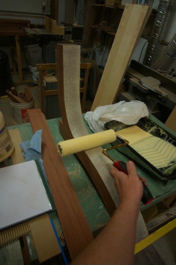
Thank goodness my friends Aric and Dave showed me the benefit of applying glue using a paint roller.  I can't imagine any better way to apply glue evenly to large surfaces quickly.  Once the glue is ready the laminations are clamped in the form.  Clamp blocks with a concave face are used to distribute pressure better.  A flat surface would only apply pressure on the tangent of the curve, but by having a concave surface (even if the curve is greater than that which it mates with) each block has two contact points rather than one.  Even with the blocks to spread out the pressure it takes many many clamps to put the laminations in the forms. 

Gluing up the Laminae

Clamp Blocks to Distribute Pressure
Formed up and Ready for the Wait

Once the laminations are completed they are edge jointed and then ripped true on the table saw.  The first component is now completed. 

Trimming the Edges of the Laminations
The second half of the perimeter section forms the top portion.  It is a curved section as well but the curves are not parallel so it is not as conducive to being built as a lamination.  I built it out of solid stock 2" thick.  The pieces were cut slightly oversize on the bandsaw and then pattern routed to match.  The tricks I have come to rely on for pattern routing include using 3 screws for reference points to ensure consistency, using some double sided tape and sand paper to help keep the pieces in place, and the change to using the newer Bessey auto adjusting toggle clamps.  Other than that I just like to try and use the two sides of a peice of MDF so that I don't mix things up and have fewer jigs and forms piling up. 

Pattern Matching the Top Components
Once the pieces are all routed identically, a recess needs to be routed to one inch from the top surface for the mounting bracket to attach to.  Also, there is a 1/8" thick strip glued onto the inside of the curve one inch down fromthe top surface.  This is only being added as a reveal to keep people from seeing through the thin gap between the ring and the panels. 

Routing out the Mounting Bracket Recess
Gluing on the Reveal Strip
Now that the top component is completed the two parts can be joined together.  A set of 1/4" holes are drilled in one half of the pair and then a set of center finders are used to transfer the location to the other half.  Once the second half of the holes is drilled 1/4" dowels are used in to align the parts during glue up. 

Aligning the two Parts of the Curve with 1/4" Center Finding Pins and Dowels
All Six of the Perimeter Sections Glued Up
Once the glue is set it is time to clean up the surfaces.  Resulting from there being two components coming together there is a glue line about one third of the way down from the top surface.  To hide this and to provide nice continuous grain around the perimeter the outer face of the curve was cleaned up so that it can have a skin of quarter sawn wood can be applied to it. 

Fairing the Outer Surface for the Addition of the Skin
Gluing up the Quarter Sawn Skin
Clamp Blocks and Blue Foam for Even Pressure
Once the skin has been applied to the perimeter section I was finallly done building the piece.  The piece was ripped to a final width of 5 and 1/4" and each end is trimmed and mortised.  This trim cut is one of the more stressful cuts in the whole process because it is done 12 times, creating 6 sequential joints.  Any errors in the angle of the cut and the subsequent mortise which needs to be square to the cut will only be compounded as the pieces are assembled.  Below is the jig I used to hold the piece while trimming, it is just a sled with support block and toggle clamp.  Once the trim cut is made I left the piece in the sled and brought a Festool Domino to the work so that it is done while the face of the joint is still square to the table. 

Trim Cutting the Ends of the Perimeter Sections

Using a Festool Domino to Mortise the Perimeter Sections
Floating Tenons Used in the Perimeter
Seeing the ring come together with very minimal tweaking required to the joints was fantastic to see.  The critical measurement out of all this was the distance from the inside corner of a joint to the inside corner of the opposite joint.  I was shooting for a measurement of 64 5/8".  Imagine my excitement when I hit all three of these within 1/32".

Gluing up the Parts to Make the Ring
Nailed It!


The Panels - Completion

As of last post the panels were built but they still need some mortises for assembly.  The first is to excavate a quarter inch recess on the underside of the panel for where the mounting plates will be let in.  The original templates used to create the panels also had the mounting plate profiles so they were held in place with double sided tape again and the perimeter defined with a quarter inch bit.  

Verifying Depth of Perimeter Routing
Perimeter Routed and Template Removed
Once the perimeter was defined the template was removed and a half inch bit was used to remove the remainder of the waste.  It is a little bit painful to watch all that beautiful veneer disappear after having so recently applied it. 

Recess Completely Excavated
The panels also need alignment slots and tabs.  I will be installing custom milled solid brass inserts which will mate with each other and help ensure that the panels are aligned with one another and also help support each other. The slots are 3/8 of an inch deep, 1/2 an inch tall and 3.5 inches long.  To create the mortises a rabbetting bit was used and a jig to control the length of the cut was built.  The jig references to the ends of the panels to make sure that the positions of the mortises remains consistent time after time.

Template and Mortise on a Panel
All the Mortises for the Alignment Inserts
The panels are now ready for sanding.  Oh my gosh soooo much sanding.  I spent three days listening to country music on the radio over the weekend but when it came to sanding, country music just wasn`t cutting it anymore.  I had to switch things up so I decided to go to some techno.  This led to a good friend at work discovering perhaps the best woodworking pun I have yet heard.  Simply the name of a song - Sandstorm, by Da Rude.  Nuff said. 

Once the sanding was complete it was time to add some edging to the perimeter of the panels.  This serves a couple purposes.  The edging protects the fragile end grain of the panels from some of the wear and tear that could prematurely affect the table.  The fact that I was able to use of beautiful ebony for this detail adds just a little punch visually as it really helps frame the table.  

The edging is just a little over 1é8 of an inch square.  The rabbett for its insertion was made with a trim router and the oversize edging was then clamped into place with masking tape.  

Trimming the Ebony Edging to Length
Routing the Rabbett for the Edging
Clamping the Edging with Masking Tape
All the Panels with Edging in Place
Once the edging has been glued in place the tape is removed and the edging needs to be flushed to the panels.  The trim router was used bring the ebony close to flush, then a scraper card to finish the flushing process.  The edges of the card scraper were taped to prevent scratching the veneer surface.  
Once trimmed flush the area was lightly sanded to blend the surfaces with the existing finish. 

Flush Trimming the Ebony
Using the Scraper Card to Finish off the Flushing
The Finished Edge
The Panels Mocked up in Their Places with Ebony Edging