Monday, 3 March 2014

Maloof Rocker - Continued

With the bulk of the construction done it is time to move on to the sculpting of the chair.  I won't go over everything, all over the chair, just a sample.  The bulk of the material removal was done with a grinder fitted with a carbide grinding wheel wheel.  I was absolutely amazed at how fast this tool was able to waste away wood.  Next, it was onto a 50 grit sanding wheel, and then on to finessing the sculptured joints by hand with rasps, files, and sand paper.  

Front Leg to Seat Joint Before Shaping

After Initial Shaping with Grinder

Arm Before Shaping

Arm After Initial Shaping With Grinder

Refining the Arm and Seat to Leg Joint with Rasps and Files

Starting to Look Decent
With the shaping completed I moved on to working on the headrest.  The locations of the spindles entry into the seat is marked and punched with an awl.  The locations of the spindles entering the headrest is marked as well and then the headrest is temporartily clamped into position so that the angles of the spindle's entry can be transfered to the headrest.  Once the lines have been transferred to the headrest, they can be sighted down for the angle of drilling into the seat.  

Sighting Down the Headrest Lines to Drill the Seat Spindle Holes
The headrest is then taken out of the chair to the drill press.  The lines drawn on the headrest are sighted as the drill bit is lowered to ensure the tilt on the drill press table matches the angle of the spindle hole. 

Sighting the Alignment of the Hole
With the holes drilled the shaping of the headrest can begin.  The headrest is clamped to the bench and  the usual routine of grinder through rasp and sandpaper was used to shape the portion of the headrest which will be inaccessible when the spindles are installed. 

Rounding Over the Headrest
With the headrest ready for installation it is time to finish preparing the spindles.  The spindles were roughed out on the bandsaw and the round over on the back formed with a router.  They were initially built overlong and are trimmed on an individual basis.  Both ends of the spindles go into 1/2" diameter holes so rasps are used to shape the ends of the spindles from roughly 1/2" by 1/2" square to circular; a test block with a 1/2" hole is used to check for fit. 

Shaping the Ends of the Spindles
The spindles are epoxied into place, to help with squeeze out the seat and headrest were taped.  The epoxy was mixed up with the addition of some sawdust to help it match the chair and allowed to cure for a day.  

Tape Protecting the Seat from Epoxy

Spindles in and Ready for Rockers

Sunday, 23 February 2014

Maloof Rocker

Some time back I became enamored by the rocking chairs made by Sam Maloof.  Then. about two and a half years ago I decided to go for it and build one.  Many of the techniques were new to me, cutting the Maloof joint with splayed legs and the use of rasps to sculpt the joinery to name a few.  With so many new techniques to explore I decided I could use a little guidance; so I purchased a set of plans/DVD from Scott Morrison out of Montana.  I won't go into details on the plans themselves, suffice it to say that Scott was quite thorough and I'd definitely recommend his plans to anyone interested.

For some reason, this has been a project which has repeatedly been set aside as other deadlines and priorities loomed overhead.  Thus, the rocker developed in spurts and the photography along the way was inconsistent to say the least.  With that being said I'll show what I can and you'll just have to fill in some blanks or contact me with questions about the stuff I had to skip over.  There will be a few posts describing the process as I get the writeup for each stage completed.  

First step of course was to break out stock.  Using a set of full size templates and the bandsaw made it easy to mix and match to get the best use of materials.  

Breaking up Stock

All the Parts Broken Up
Unfortunately, here is a large gap in the project; and when I say large - I mean really large. 

So, by way of getting caught up on a few things.  The seats are glued up from 5 boards, there is a 3 degree slope cut on each of the seams to start creating the scooped shape of the seat.  Then, a grinder and sanders are used to waste away the bulk of the wood while creating the saddle.  The real fun was in cutting the joinery for the legs.  Notches were cut out of the sides up near the front and in the corners at the rear; then, rabbeting bits were used to recess the top and bottom surfaces and create the first half of the Maloof joint.  The joinery for the front legs to the seat was relatively simple.  A dado is cut to match the ledges on the seat left behind by the rabbets.  With that complete the legs are turned on the lath and the lower portion is brought to a diameter of 1-1/4", and the top portion to 1-3/8".  The tops of the front legs need to be cut on a slope down towards the back of the chair at 13 degrees to allow a flush surface for the arms to join with.

Trimming to Length and Slope
When joining the front legs to the seat I used two pipe clamps; one above and one below; which allowed me to adjust pressure and ensure that the legs are held parallel to each other and perpendicular to the seat. 

Gluing the Front Legs to the Seat
When joining the rear legs to the seat it is important to control the splay of the legs and ensure that they are symmetrical.  To make sure of this a mock headrest with 5 degree slopes on each end was used to align the legs.  Things are finally starting to look like a chair.  

Rear Legs Being Glued tot he Seat
With the rear legs glued into place it is time to attach the arms.  You may notice that the arms are not shaped at this point, that will be taken care of after installation.  The first step to install them is to trim the ends of the arms to match the slope of the joint with the rear legs. 

Trimming the Back of the Arm
The arms are installed with a screw through the rear leg and a dowel in the front leg. 

First, the joint with the front leg.  There is a 1/2" diameter hole in the top of the leg, a center finder is placed in it and then the arm is set into place and the dowel position is marked with the center-finder.  Once that is completed, the arm is held in position and a straightedge is used to sight down the leg and draw the slope at which the dowel will be inserted into the arm.  This is then drilled and a dowel is epoxied in place. 

Marking for Dowel Alignment
To make the joint with the rear leg the joint is held firm with a couple clamps.  Then, a stepped hole is drilled through the rear leg so that in addition to the glue in the joint,  a screw can draw the arm snug. 

Clamping the Arm in Place to Drill through the Rear Leg
Some of you may have noticed that some of the photos are of chair parts made of walnut, and some are made of cherry.  There is of course a reasonable / ridiculous reason for this.  I figured that as long as I was setting up angles for cuts on the table saw and such I might as well get the most out of all the setup; so I've been working on three chairs simultaneously.  Well, up to now anyways.  Now that the cutting and assembly is done, the next major phase is sculpting of the joints and I am now working on one chair to completion.  

Three Initial Assemblies all Glued up and Ready for Shaping

Wednesday, 12 February 2014

Roorkhee Chair

About 4 years ago I was in Egypt and while wandering through some shops in Cairo I saw a chair which I would have described as the best looking lawn chair I'd ever seen.  Then, a couple years back Chris Schwarz wrote an article for Popular Woodworking and I saw that lawn chair on the cover of the magazine.  It turns out that the type of chair is called a Roorkhee; and they became popular during the days of the British Campaigns as they pack up light and small.

Recently, I did come across a "modern day" version of the roorkhee while wandering through a furniture store.  It had a solid frame made of brushed steel with leather for the backrest and seat.  


A Similar Chair in a Store

Wow!!!

Many of my projects lately have run into delays, they have been complicated and long term.  So after keeping this chair inteh back of my mind for a while I decided to take a swing at it as it seemed like it might be good for woodworker looking for a "safe" project.  

The project started with a set of templates, both for the woodwork and for the leatherwork.  I made up a story board for the woodwork, one side for the legs, the other for the stretchers and back support stays. 

Woodworking Story Board for the Chair

Due to the leather forming the seat and the backrest there is relatively little wood and little woodwork compared with other chairs.  Really only 10 sticks; 4 legs which are almost identical, 4 stretchers which are all identical, and 2 back support stays.

Wood Components Roughed Out and Ready

The mortise and tenon joints for this chair are made with tapered tenons which mate with a similarly tapered mortise.  The tenons are cut onto the stretchers with a tapered tenon cutter which essentially works like a large pencil sharpener.  The mortises are cut in two stages; first a 1/2" diameter hole is drilled through the leg.  Second, a tapered reamer is used in a hand brace to enlarge the mortise and make it cone shaped, matching the taper of the tenon on the stretchers.  


Tapered Tenon Cutter


Tapered Reamer

This was the only part of the woodworking that was a little outside the norm I figured I'd move right on to the leatherworking which was quite a bit of fun.  I found the leatherwork to be pretty easy.  Like much of woodworking it comes down to careful layout and using sharp tools.   

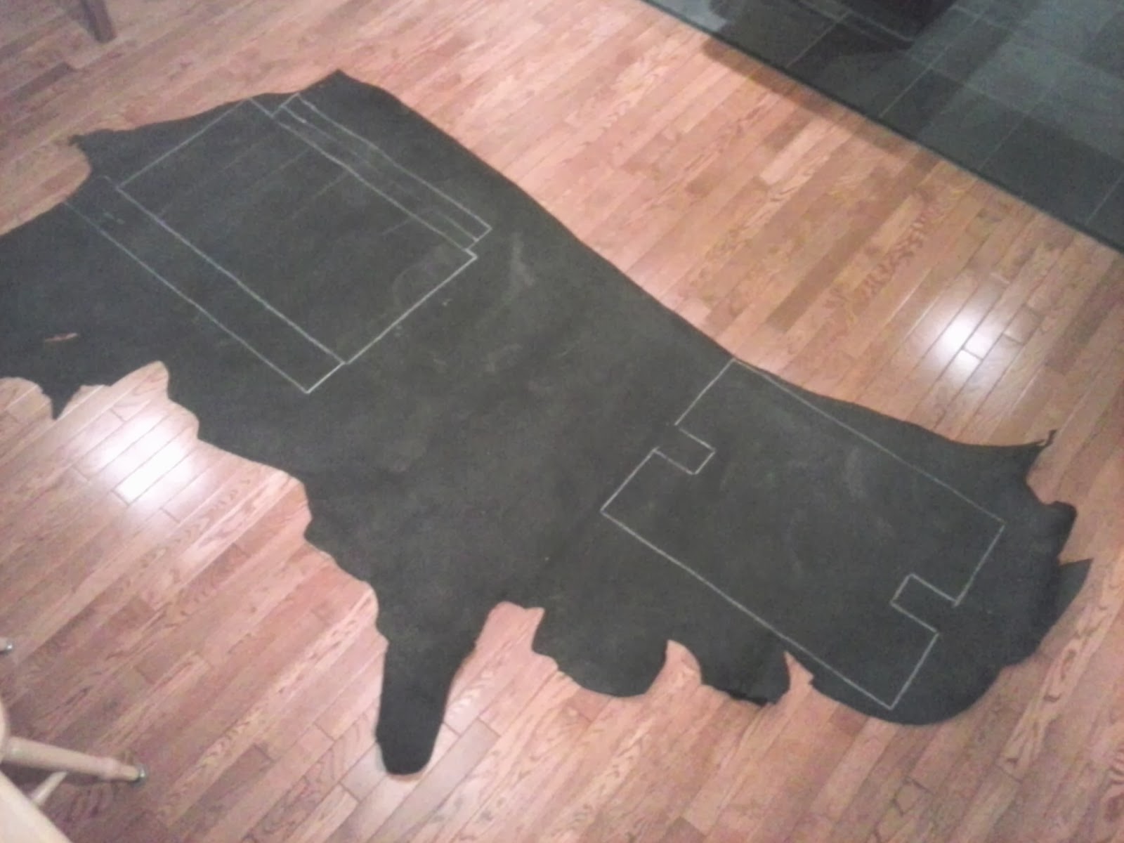
The leather work started with some templates which I could arrange over the leather for optimal use.  Just like wood, leather is natural and can have defects which need to be worked around.  The templates let me work around the defects while trying to keep the most efficient offcuts.  I found chalk to be the only thing which marked the leather well, a straight edge and sharp utility knife were all that were needed to cut the leather. 


Templates of the Leather Components

The Hide Ready for Cutting

Leather Parts Cut Out and Ready to Work

To join the leather two basic tools are all that were needed.  A leather punch to make the holes (which are sized to match the rivets going through), and an anvil with matching setter to install the rivets or eyelets.  

The leather punch is pretty straightforward.  It works just like a pair of pliers a pops out perfect little holes every time. 

Leather Punch

The anvil (pictured below) is placed on the table, both halves of the rivet or eyelet are set into place and then set over the anvil.  Then, the setter is placed on top and hit with a hammer a couple times to place the rivet.  The anvil and setter force the post of one half of the rivet to bend and couple with the other half of the rivet.  Beautifully simple. 

Anvil and Both Halves of the Eyelets


I don't know what it is but I have to admit there is something sexy abut black leather detailed with silver eyelets and rivets.  
Eyelets for the Seat

The arms attache to the chair by means of a pair of ball nuts on the front and back legs.  The leather is stretched over the tops of the legs and holes with slits to extend them slip over the ball nuts.  

Detail of the Ball Nut

The back rest stays attach to the tops of the rear legs by means of a nut and bolt which allows it to pivot to whatever angle the sitter is leaning at.  

Back of the Chair

The lacing on the underside of the seat can be tightened over time to compensate for any stretching that may develop in the leather. 

Lacing on the Underside of the Seat


I had a few friends come over a couple days ago and encouraged them to try out the chair as I wanted to know if they found it comfortable.  I was quite pleased with the results as there were 4 people who tried it out and 2 of them almost instantly said "Wow" upon sitting down.  I admit as well that I do find the chair to be very comfortable, the longest sit I've had so far is 45 minutes and it was great for the duration.   


Finished Roorkhee Chair


Thursday, 28 November 2013

A Day With Konrad Sauer

Last Saturday (Nov 23rd) I woke up at 5:00 AM, I never wake up at 5:00, especially on a Saturday.  However, I had a very good reason.  Konrad Sauer paid a visit to Edmonton's Northern Alberta Woodworker's Guild.  For anyone not familiar with Konrad's work I highly recommend that you check it out, Sauer and Steiner.  He is a maker of exquisite hand planes and custom furniture. 

Konrad gave presentations on Friday evening about his plane making process, one on Saturday morning about hand shaping (using mostly rasps and files) of plane parts and table legs, and a third presentation in the afternoon about his design process.  

I was unable to attend the session on Friday but a few of my take-aways from the Saturday sessions included.  

- Similar to a handsaw, a hand plane has hang (how the tool naturally rests in your hand), and that a three finger pistol grip is generally the way to go for both control and eliminating death grip.  
- I had seen in Konrad's blog that he sometimes uses a machinist's vise to hold a twin screw woodworker's clamp which then holds the workpiece.  Seeing the setup in person was a real eyeopener as to how versatile and useful it is.  
- When designing his personal table, the design process included not just a mock up of the table in the room; The table top was set into place and the chairs were set around it and the chairs, people's feet and knees were drawn onto a map on the shop floor so that the table feet and legs could be designed around where people would sit.  

A definite highlight for the day was having dinner after the sessions were over.  There was six of us who were able to make it and getting to know another handful of devoted craftsmen is always a real treat.  Sharing thoughts on craft and design is always great dinner conversation and the opportunities for it don't come by nearly often enough.  

All this being said, by far the most enjoyable time in the day was having the opportunity to try out several of Konrad's planes.  They were all exquisitely crafted and a real joy to use.  I could wax poetic about them for a page and not come close to describing how great they are to use; a perfect marriage of form and function where both are allowed to shine as brilliantly as the sun.  Suffice it to say that if you get the chance to use one, take it! 

Konrad Shaping a Table Leg
A Selection of Beautiful Hand Planes

Sunday, 24 November 2013

A Couple Small Projects

Well the expanding table is sill in the works, though progress comes in very small spurts which are spaced far apart.  After some rearranging in the shop I have been able to work on a couple small projects to satisfy my creative outlet.  

Quite some time ago my dad showed me a new knife block he had; I loved how it didn't have designated slots and was instead a box filled with a bunch of polypropylene rods.  Look here to see what I mean.  With how cool the knife block is I also knew it could be so much cooler if made out some nicer wood so I got to work.  

I decided to make the box with rabbett joints and a plywood bottom 9" down from the top.  The box was built of African Paduak which irridesces with a rich red color and I added in some African Blackwood along the edges.  I don't know how I didn't think of this before but to glue up the box I "clamped" it using plastic wrap.  It worked amazingly well, providing consistent pressure along the joints and allowing for very easy alignment adjustments. 

Saran Clamp
Finished Up and Ready to Go
The Knife Block in Use

Another small project I did recently was a tea light candle holder.  The carved tree I inserted into the back of a chair of a deskset earlier this year has become a personal favorite.  With the inspiration from a friend's recent floor lamp project I decided to combine the two.  


The project started with taping a few pieces together and a pattern on front,  With some pilot holes drilled a fret saw makes takes care of removing the waste. 

Multiple Panels Cut at Once with a Fret Saw


I went to a craft store and purchased some rice paper and rice glue, a thin coat of glue was all that was needed to apply the paper.  Note that the right edge of the two panels in the photo below are free of paper.  This needs to stay clear so that the butt joints will have wood to adhere to and there won't be a layer of paper visible on the outside.  A simple block of wood with a few rabbetts provides the base for the candle fixture. 


Applying the Rice Paper


Finished Components


Finished Candle Lantern


Friday, 18 October 2013

Replacement Nuts and Bolts

There hasn't been much progress on the table to report in quite a while.  This has been largely due to the need to get two of the central components re-milled to accept some new linear bearings in place of the existing bushings.  At long last we got the part fixed and got some new washers and the linear bearings to install.  This of course necessitated disassembling the entire table to send the parts out to get fixed and a complete reassembly. 

The new linear bearings will allow the existing rods to slide up and down better than the originally used press fit bushings.  The most common use of bearings is in a pair or rings which allows for rotational movement.  Linear bearings allow shafts to slide through tubes.  In this case the tubes have five tracks of bearings on which the steel rods will travel. 

Bushing Holes Enlarged to Accept the New Linear Bearings
Linear Bearing and Retaining Ring


Central Components with New Bearings Installed
You may be able to see some plugs in the centers of the linear bearings, these stay in place to keep the ball bearings in place until assembly when the rods push them through.  

With the bearings in place we are able to re-assemble the rest of the table including all the support and actuator arms and then proceed on to the panels. 

The Mechanism Re-assembled and Ready for the Panels

Central Star and Arrow Wedges in Place


Pie Wedges in Place, the Star and Arrow Wedges are Stored Underneath

In Transition Between Small and Large


Small Configuration, Loose Assembly of Panels

Since this is a table with moving parts it would be wrong to not include at least a little video of the piece in action.  

This first video shows the center star and arrow shaped wedges in action.  You may be able to catch a glimpse of some of the mechanisms underneath.  


This video shows all the panels in action.  Hope you like it!


It has taken us a long time to get where we are now, and there is still lots to do.  Two notable tasks will be the final alignment of all the panels and the installation of the apron ring which will conceal the mechanisms from view.  I imagine it will be quite a while before everything is actually 100% done, it feels like we've been sitting at 99% for months.