Thursday, 6 June 2013

Perimerter Ring

So because this table expands and contracts to different diameters there is a perimeter ring added which raises in and out of position.  The ring performs a couple of functions.  The first is that when the table is small it allows the table to remain circular, otherwise the panels which are circular when large would create a slightly lobate perimeter.  The second function is concealing the mechanisms that allow for the expansion and contraction to occur.  The perimeter is 5 1/4 inches tall which keeps the mechanisms concealed when small, and when large the ring drops down to allow the expansion and continues to conceal the mechanisms. 

The most time consuming part of the ring components is the bent lamination.  I know that some people build bending forms with a curve which is tighter than desired to allow for the springback that often results from quickly cycling parts through the bending form.  The way I was taught and have experimented a little as well eliminates this.  I have found that by building my bending forms to the exact curve I need and keeping the parts in the form longer the spring back is eliminated.  If we leave a blob of glue on a table and poke it in an hour there will be a skin on the surface but it will still be mushy inside, come back in half a day and it is harder but still soft, but if you come back in a day it will likely be hard, only moved with a chisel.  Using this logic I leave my laminations in their bending forms for two days.  This way, the parts don't move at all after removal and they are all identical.  As a result of the two day time frame, and there being six components I knew it would take 12 days to work through all these parts.  A good part to start at the beginning of the project. 

The process started with resawing a pile of 1/8" thick by 4" wide strips, each lamination is made up of 8 laminae to come out to a full 1" thick when completed. 

Stock for Bent Lamination
The bending form is made up of 9 layers of 1/2" MDF.  The first is faired to the exact curve desired, the rest are added two at a time and then pattern matched to the first.  Also, a shelf was added to the bottom of the form to provide a reference surface for the bottom edge of the lamination. 

Bending Form for the Bent Lamination
Thank goodness my friends Aric and Dave showed me the benefit of applying glue using a paint roller.  I can't imagine any better way to apply glue evenly to large surfaces quickly.  Once the glue is ready the laminations are clamped in the form.  Clamp blocks with a concave face are used to distribute pressure better.  A flat surface would only apply pressure on the tangent of the curve, but by having a concave surface (even if the curve is greater than that which it mates with) each block has two contact points rather than one.  Even with the blocks to spread out the pressure it takes many many clamps to put the laminations in the forms. 

Gluing up the Laminae

Clamp Blocks to Distribute Pressure
Formed up and Ready for the Wait

Once the laminations are completed they are edge jointed and then ripped true on the table saw.  The first component is now completed. 

Trimming the Edges of the Laminations
The second half of the perimeter section forms the top portion.  It is a curved section as well but the curves are not parallel so it is not as conducive to being built as a lamination.  I built it out of solid stock 2" thick.  The pieces were cut slightly oversize on the bandsaw and then pattern routed to match.  The tricks I have come to rely on for pattern routing include using 3 screws for reference points to ensure consistency, using some double sided tape and sand paper to help keep the pieces in place, and the change to using the newer Bessey auto adjusting toggle clamps.  Other than that I just like to try and use the two sides of a peice of MDF so that I don't mix things up and have fewer jigs and forms piling up. 

Pattern Matching the Top Components
Once the pieces are all routed identically, a recess needs to be routed to one inch from the top surface for the mounting bracket to attach to.  Also, there is a 1/8" thick strip glued onto the inside of the curve one inch down fromthe top surface.  This is only being added as a reveal to keep people from seeing through the thin gap between the ring and the panels. 

Routing out the Mounting Bracket Recess
Gluing on the Reveal Strip
Now that the top component is completed the two parts can be joined together.  A set of 1/4" holes are drilled in one half of the pair and then a set of center finders are used to transfer the location to the other half.  Once the second half of the holes is drilled 1/4" dowels are used in to align the parts during glue up. 

Aligning the two Parts of the Curve with 1/4" Center Finding Pins and Dowels
All Six of the Perimeter Sections Glued Up
Once the glue is set it is time to clean up the surfaces.  Resulting from there being two components coming together there is a glue line about one third of the way down from the top surface.  To hide this and to provide nice continuous grain around the perimeter the outer face of the curve was cleaned up so that it can have a skin of quarter sawn wood can be applied to it. 

Fairing the Outer Surface for the Addition of the Skin
Gluing up the Quarter Sawn Skin
Clamp Blocks and Blue Foam for Even Pressure
Once the skin has been applied to the perimeter section I was finallly done building the piece.  The piece was ripped to a final width of 5 and 1/4" and each end is trimmed and mortised.  This trim cut is one of the more stressful cuts in the whole process because it is done 12 times, creating 6 sequential joints.  Any errors in the angle of the cut and the subsequent mortise which needs to be square to the cut will only be compounded as the pieces are assembled.  Below is the jig I used to hold the piece while trimming, it is just a sled with support block and toggle clamp.  Once the trim cut is made I left the piece in the sled and brought a Festool Domino to the work so that it is done while the face of the joint is still square to the table. 

Trim Cutting the Ends of the Perimeter Sections

Using a Festool Domino to Mortise the Perimeter Sections
Floating Tenons Used in the Perimeter
Seeing the ring come together with very minimal tweaking required to the joints was fantastic to see.  The critical measurement out of all this was the distance from the inside corner of a joint to the inside corner of the opposite joint.  I was shooting for a measurement of 64 5/8".  Imagine my excitement when I hit all three of these within 1/32".

Gluing up the Parts to Make the Ring
Nailed It!


The Panels - Completion

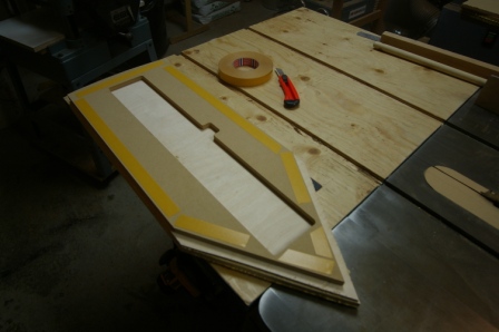
As of last post the panels were built but they still need some mortises for assembly.  The first is to excavate a quarter inch recess on the underside of the panel for where the mounting plates will be let in.  The original templates used to create the panels also had the mounting plate profiles so they were held in place with double sided tape again and the perimeter defined with a quarter inch bit.  

Verifying Depth of Perimeter Routing
Perimeter Routed and Template Removed
Once the perimeter was defined the template was removed and a half inch bit was used to remove the remainder of the waste.  It is a little bit painful to watch all that beautiful veneer disappear after having so recently applied it. 

Recess Completely Excavated
The panels also need alignment slots and tabs.  I will be installing custom milled solid brass inserts which will mate with each other and help ensure that the panels are aligned with one another and also help support each other. The slots are 3/8 of an inch deep, 1/2 an inch tall and 3.5 inches long.  To create the mortises a rabbetting bit was used and a jig to control the length of the cut was built.  The jig references to the ends of the panels to make sure that the positions of the mortises remains consistent time after time.

Template and Mortise on a Panel
All the Mortises for the Alignment Inserts
The panels are now ready for sanding.  Oh my gosh soooo much sanding.  I spent three days listening to country music on the radio over the weekend but when it came to sanding, country music just wasn`t cutting it anymore.  I had to switch things up so I decided to go to some techno.  This led to a good friend at work discovering perhaps the best woodworking pun I have yet heard.  Simply the name of a song - Sandstorm, by Da Rude.  Nuff said. 

Once the sanding was complete it was time to add some edging to the perimeter of the panels.  This serves a couple purposes.  The edging protects the fragile end grain of the panels from some of the wear and tear that could prematurely affect the table.  The fact that I was able to use of beautiful ebony for this detail adds just a little punch visually as it really helps frame the table.  

The edging is just a little over 1é8 of an inch square.  The rabbett for its insertion was made with a trim router and the oversize edging was then clamped into place with masking tape.  

Trimming the Ebony Edging to Length
Routing the Rabbett for the Edging
Clamping the Edging with Masking Tape
All the Panels with Edging in Place
Once the edging has been glued in place the tape is removed and the edging needs to be flushed to the panels.  The trim router was used bring the ebony close to flush, then a scraper card to finish the flushing process.  The edges of the card scraper were taped to prevent scratching the veneer surface.  
Once trimmed flush the area was lightly sanded to blend the surfaces with the existing finish. 

Flush Trimming the Ebony
Using the Scraper Card to Finish off the Flushing
The Finished Edge
The Panels Mocked up in Their Places with Ebony Edging


Monday, 20 May 2013

The Panels - Veneering

When the edging was applied it was about 1/32" wider then the panels, this is to allow for flush sanding with the panels.  When this has been completed I was ready to apply the veneer.  For this project the veneer is applied to one side at a time so that the vacuum bag doesn't have the chance to break and splinter and overhanging veneer which would otherwise be on the top surface.  The bottom is veneered, trimmed flush and then the panel is flipped and the top is veneered. 

Pressing the Veneer on bottom of the Panels
On the first round of pressing veneer I made a mistake and formed a few long bubbles in the veneer which needed repair.  The process I used was to moisten and heat the veneer/glue which allows the glue to release and the veneer to be pressed flat manually.  The glue can then bond to the newly flattened veneer. 

A Bubble Ridge in the Veneer in Need of Repair
Paper Towel with Water
Ironing the Papertowel to Add Steam to the Bubble
Using the Iron as a Hot Veneer Hammer to Reactivate and Bond the Glue
Bubble - Before
Bubble - After
The First Panels Veneered on Both Sides are Ready to Go


Pressing the Center Star

After pressing all the veneers I took all the panels over to my friend Dave's house to use his stroke sander.  This quickly surfaced all the panels to 180 grit leaving only to finish sand the veneer surfaces, hand sand the edges and break the edges. While at Dave's he suggested we spread out the parts on the driveway to have a look and see how things will look when completed.  Keeping in mind that there still needs to be a finish sanding done and then lacquer applied we were pretty excited. 

Full Size Table

Full Size Table With Some Gaps to See the Parts Better
Center Star in the Sun

The Panels - Continued


So up until now the panels have all been kept a little oversize.  I lucked out and was able to get a set of templates for the finished dimensions of the parts manufactured on a CNC machine.  


A Single 4x8 sheet of 1/2" MDF held all the Templates
Templates Ready to Go

The templates are attached to the oversize parts using double sided tape.  Once the parts have been matched to the templates they are at their finished dimensions.  However, an allowance for the addition of solid wood edging needed to be made.  The full size parts were profiled with a 1/8" rabbeting bit and then matched to the reduced dimension, this leaves room for 1/8" thick edging. 

Double Sided Tape on the Template
Bearing Bit to allow for Pattern Matching

All the panels Ready to go
A Mountain of Sawdust from the Patten Routing

The edging is added in stages so that one joint can be matched to the next.  The overhang from the first peices is trimmed flush witht he adjoining edge and then the next piece can be added.  Regular masking tape is used to clamp the edging in place.  As it is applied it is stretched to privide pressure. 
 
Center Star with Edging in Progress

A Stack of Partially Edged Components

Not everything always goes as planned, one of the pie wedge components had a portion of the curved edging delaminate.  To fix the problem the old glue was cleaned out of the joint, new glue added and a bar clamp to apply more pressure to make sure it takes hold. 
 
Fixing the Delaminated Edging

Use of a Block to Prevent Marring the Surface


Tuesday, 14 May 2013

Expanding Dining Table

So I have been working on a dining table for quite some time now.  Actually, it's been a couple of years.  The project is a radially expanding dining table.  The original concept is credited to Robert Jupe who came up with the idea back in 1835.  

Following are some renderings from the computer model used to develop the parts.  The internal mechanisms for the table are being custom machined. 


The Table When Small
The Table While Expanding
The Table When Large

When small, the table has a diameter of five feet and will seat eight.  Then, after expansion, the table is seven feet diameter and seats twelve.  

As a starting point for the project I'll begin with the panels.

The table requires six pie shaped wedges, six arrows, and a twelve pointed star in the middle to bring it all together.  The first step was to make rough templates of the parts, the templates were used to make the initial panels.  These panels were made slightly oversize and then trimmed to size based on templates cut out on a CNC machine.  Then edging will be added and veneer pressed on both sides.  


Miter Sled Making the Rough Template

Bandsawing to the line for the Rough Template

The substrate used for the table top components is baltic birch.  It is made up of a lamination of 1/4", 1/2", and then 1/4".  The 1/2" baltic birch has its surface grain oriented the same as the desired orientation for the veneer and the two sheets of 1/4" are orthogonal to that, this is to help ensure the stability of the panels. 

Stack of Parts Ready for Lamination. 

The Components are in the Press, Masking Tape Helps with Alignment


First Set of Lamination Completed

The perimeter of the components is edged with 1/8" thick strips of solid wood.  The edging was made on the table saw / band saw / thicknesser, nothing too special going on there in terms of techniques.  

Solid Lumber Delivery for the Table,   12'6"

1/8" Edge Materials
For the top of the panels a high grade veneer was chosen, the underside of the tabletop will also be veneered with the same species (Bubinga), but with a lower quality. 

Kevazinga Veneer for the Top of the Table


The edges of the veneer needs to be jointed after the initial cutting, this shooting board allows the clamping of multiple sheets of veneer at once to help ensure consistency. 

Shooting Edges on the Veneer
Once the edges of the veneers are jointed on the shooting board the veneers can be arranged as below to create a sunburst pattern.  The pattern below in the photo can be expanded for as many segments as needed, and ensures that a sheet of veneer is no more than two away from the original sesequence.  Then by flipping alternate veneer sheets (the circled numbers) the edges will match up and the sunburst is complete.  


The Pattern Used for the Sequence of Veneer Sheets
Sunburst Pattern for the Center Star